5. Crossovers - www.hifilounge.eu
Main menu:
- Home
- General
-
Speakers
- Basics
- Speakers
- Headphones
- Subwoofer
- Elektronics
- Surround
- Photography
- Infos
5. Crossovers
Speakers > Speakers
In order to build a loudspeaker with a homogeneous transmission behaviour, usually several chassis are used. The allocation of the respective working ranges is done by the crossovers.
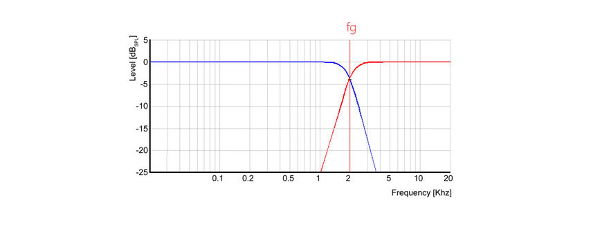
Figure 1: Crossover transmission for bass river (blue) and tweeter (red)
How do the circuits of crossovers work? How do the crossovers of active and passive loudspeakers work? This section is intended to provide answers to these questions.
Crossovers have two primary functions.
Filtering the signals from too high and/or too low frequencies to make the responsible chassis work only in the optimal frequency range
Correction of the transmission characteristics of the loudspeakers, including, for example, frequency response unevenness of the drivers due to resonances or frequency response ripples caused by baffles such as the baffle step
Analogue switches
Most crossovers work analog and are based on the clever interconnection of coils, resistors and inductors. The alternating current resistance, also known as impedance, behaves very differently between the components depending on the frequency. The reason for this is a different primary property which dominates the behaviour of the component.
- The primary property of the component "resistance" is the ohmic resistance - the impedance is independent of frequency.
- The primary property of a coil is the inductance, therefore the impedance increases with increasing frequency.
- With a capacitor the capacitance is the dominant property, the impedance decreases with the frequency
Often the components and the primary property are equated, e.g. a capacitor and a capacitance are often used synonymously. However, real components are not only characterized by their primary properties. For example, each coil also has an ohmic resistance of copper and the windings of a coil have a capacity to each other.
An ohmic resistance converts electrical power into thermal power (=heat). Capacities and inductors do not produce heat, the resistance of these components to the electric current (= impedance) is due to their ability to store electrical energy for a short time and to release it again after a time delay.
Wiring of analog turnouts
The following shows a simple crossover with one coil. The coil has an impedance which increases with increasing frequency.
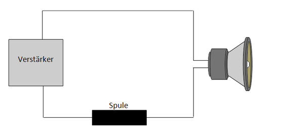
Figure 2: Simple low pass with one coil
In Figure 1 the amplifier provides a constant voltage. At low frequencies, the coil is little more than a well-conductive piece of wire and is electrically almost invisible. As the frequency increases, the impedance of the connected load through the coil increases significantly. According to Ohm's law

with the voltage U, the impedance Z and the current I, the amplifier will send less and less current into the circuit - and the magnetic driving force of the voice coil will become smaller and smaller due to the decreasing currents.
By dimensioning the coil, the cut-off frequency of the filter can be influenced. If the filter is to have a higher edge steepness, more components must be used. An additional capacitor can fulfil this function in the example - see Figure 2.
The coil continues to perform the same function as in Figure 1. At low frequencies, the capacitor is virtually an interruption in the circuit - through which logically no current can flow.
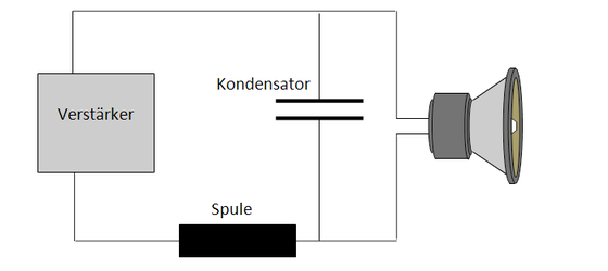
Figure 3: Simple low pass with coil and capacitor
As the frequency increases, the capacitor becomes increasingly conductive. At high frequencies, the current is thus free to choose whether it flows through the chassis or through the capacitor. It takes the path of least resistance, which at high frequencies is logically the capacitor, the chassis is thus virtually currentless.
The quantity of effective filter elements (coils or capacitor) indicates how high the edge steepness of the filter is at the cut-off frequency - and corresponds quasi to the number of coefficients for the mean value filter presented in chapter 2.4.3 from page 63 on. Each of the components can increase the edge steepness of the filter with intelligent circuitry, but unfortunately each additional element causes additional phase errors.
- The number of coils or capacitors is described by the so-called order of the crossover. If only one coil is installed, it is called a first order crossover. This crossover would attenuate the signal by 6dB when the frequency doubles.
- 1st order crossover: separation with 6dB per octave
- 2nd order crossover: separation with 12dB per octave
- 3rd order crossover: separation with 18dB per octave
- Soft...
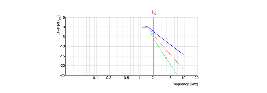
Figure 4: Different filter orders
Low-order turnouts have mainly the following advantages
The lowest phase errors are caused, accordingly the switches are characterized as correct in time
The flat separation allows simple crossovers with a low contact resistance and in the case of passive loudspeakers a high damping factor, more on this later.
However, a flat separating crossover also has disadvantages
Interference with other chassis is almost inevitable due to the wide range of applications
The thermal and mechanical load on the chassis increases, which can result in dynamic compression and reduced level stability
Digital crossovers
The "input data processing" of the crossover can be either analogue or digital. Digital crossovers use microchips (small highly optimized computers) to achieve the desired filter behavior. This solution is especially popular with hobbyists who build their own loudspeakers. In most cases the crossover can be configured on a standard PC using the included software. With a few mouse clicks any desired transmission behaviour is possible, when the saved pocket money is finally enough for the new tweeter the crossover is ready for use in no time.
A special feature of digital crossovers is that the phase response can be linearised relatively easily. A complex multi-way loudspeaker with steeply separating crossovers can be equipped with an impulse response that puts any full range driver in the shade.
The transmission behaviour of systems inevitably leads to phase errors. It doesn't matter whether the transmission behaviour is influenced by cabinet resonance or the crossover - every (!) influence on the amplitude frequency response inevitably results in the associated phase errors. The steeper a filter separates, the stronger the phase errors.
The phase errors are noticeable in that different frequency components are output with a time delay. When using digital crossovers, the first frequency components can be buffered and output with a delay as soon as the last frequency components have arrived. For real-time applications such as mixing in the studio, the maximum tolerable delay is limited, but there are no problems when listening to music alone.
Phase errors are particularly audible in the low frequencies - this is where the runtime errors are greatest. Due to the long runtimes, however, phase equalization is associated with the greatest delay times, and real-time applications can be correspondingly problematic. Closed bass loudspeakers and flat separating crossovers for the woofer reduce the problem considerably, but under these conditions phase equalization only leads to limited audible advantages.
In practice, it is much easier to implement complex filter behavior with a digital crossover - especially if the phase response also needs to be equalized.
In principle, however, the same filter behavior can be implemented with an analog crossover as with a digital crossover. In some special cases, such as the Meyersound HD-1, this even applies to active phase compensation circuits for optimizing the phase response. However, the implementation of a complex filter behavior is much easier, faster and more flexible with a digital crossover.
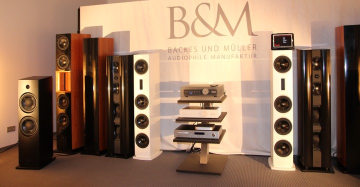
Figure 5: Digitally active loudspeakers from Backes and Müller
Figure 4 shows active loudspeakers with integrated digital crossovers from Backes and Müller. Each of the loudspeakers has several power amplifiers integrated into the housing, each power amplifier controls one chassis.
Digital crossovers can only be used in active loudspeakers. Analogue crossovers can be used in active and passive loudspeakers.
Active and passive loudspeakers
Active loudspeakers are basically all loudspeakers which have an amplifier integrated in the loudspeaker housing - and therefore need their own connection for the power supply or batteries. Every computer speaker is an active speaker.
In professional audio engineering, however, the term active loudspeaker refers to an activated crossover design. Even if the power amplifiers are not housed in the speaker enclosure, it may still be an active speaker.
With an activated crossover design, the signal is filtered in small-signal mode with extremely low currents and voltages. The signal is then amplified with a separate power amplifier for each connected chassis.
With a passive loudspeaker the filtering takes place in large signal mode, the crossovers work with the signals amplified by the power amplifier. Figure 1 illustrates the difference.
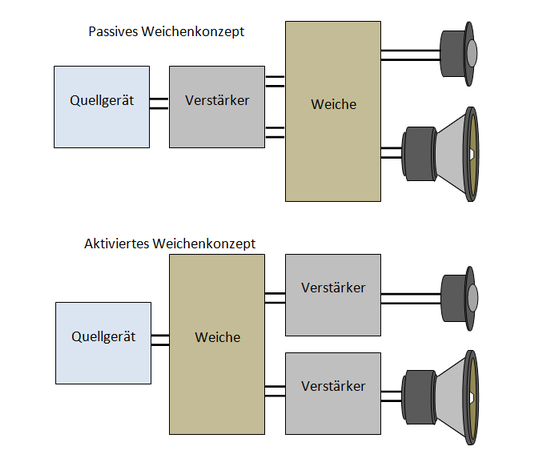
Figure 6: Active and passive switch concept
The main disadvantage of active loudspeakers is the cost. Operating each channel with a separate power amplifier is expensive.
The advantages of active loudspeakers are much more numerous.
Active equalization of the bass
At very low frequencies, very large membranes must be used so that the sound can be reproduced with sufficient volume. Below a certain cut-off frequency, which depends on the volume of the loudspeakers and the drivers, the bass frequencies become quieter and quieter.
With passive loudspeakers you have to live with this compromise. By using a resonant oscillating circuit it would in principle be possible to draw more power from the amplifier at certain frequencies and to compensate for the "getting quieter" of the chassis by adding more power. In practice, however, the use of resonant circuits is extremely difficult. The load on the amplifier is extremely high, the system can start to oscillate, the impulse behaviour becomes absolutely miserable,... a practical implementation of a low bass equalization with passive loudspeakers is therefore virtually impossible.
With active loudspeakers, low bass equalisation is a breeze. The crossover which works in front (!) of the power amplifier preferentially lets the missing bass parts pass and compensates the weaknesses of the loudspeaker with more power. Actively equalised loudspeakers require thermally and mechanically highly resilient drivers and powerful power amplifiers so that active equalisation does not lead to smoke formation. The significantly better low bass capability of active subwoofers compared to passive loudspeakers is primarily due to the active equalization.
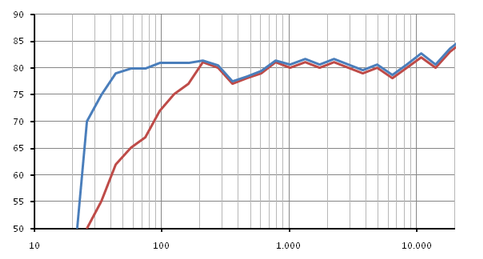
Figure 7: Basic description of bass equalisation
Damping factor
A good amplifier output stage has an internal resistance of about zero ohms. The advantage of low internal resistance is, simply put, direct control of the loudspeaker chassis.
During the lifting movements performed by a loudspeaker chassis there are different forces acting against each other.
The first force is exerted by the amplifier. The amplifier drives the moving parts of the chassis via the energised voice coils in the magnetic field of the permanent magnets in time with the music signal.
The second force is based on the mass inertia of the moving chassis elements. A moving mass wants to maintain its movement - regardless of whether the music signal wants a different direction or not.
Active loudspeakers have constructive advantages in suppressing the second undesired second force. If the diaphragm were to move further due to its own mass inertia, it would induce a voltage in the voice coil - similar to a linear motor.
However, the voltage applied to the voice coil is not decided democratically. In an active loudspeaker, the voice coil is directly connected to the power output stage - and the power amplifier throws its entire fighting weight, consisting of the power reserves of the German power grid and a negative feedback circuit architecture, into the car's bowl as it struggles for chassis control. The induced voltage of the chassis is effectively suppressed (in technical jargon short-circuited) by the output stage. In the end, the voltage will be exactly the same as the output stage. As a result, unwanted chassis movements are prevented.
Passive loudspeakers have crossovers between the power amplifiers and the chassis. The control of the loudspeaker chassis is therefore only indirect. The voltages induced by the wobbling movements of the drivers can build up more or less undisturbed somewhere in the crossover, resulting in the power amplifier having only limited control when suppressing the overshoots.
The effect is particularly audible in the frequency ranges where the movement of the drivers is most intense - at the lower frequencies. Passive loudspeakers tend to have an unclean and booming bass due to their design; with good active loudspeakers the drums often look crisper.
The resistance between amplifier and chassis is determined by the resistance of the electrical transmission elements in between. The following three resistors are usually combined and hinder the amplifier's ability to assert itself
The internal resistance of the amplifier
The contact resistance of the crossover
The resistance of the cables
Although the output stage current of passive loudspeakers has to move through the thin coiled copper wire of a crossover coil, there is a persistent belief that in real high-end systems, arm-thick power cables have to be used to connect the speakers. After all, the resistance between loudspeaker and power amplifier must be as small as possible in order to achieve a better damping factor.
The resistance of common crossovers is significantly higher than the resistance of the wiring, even with a very simple filter design.
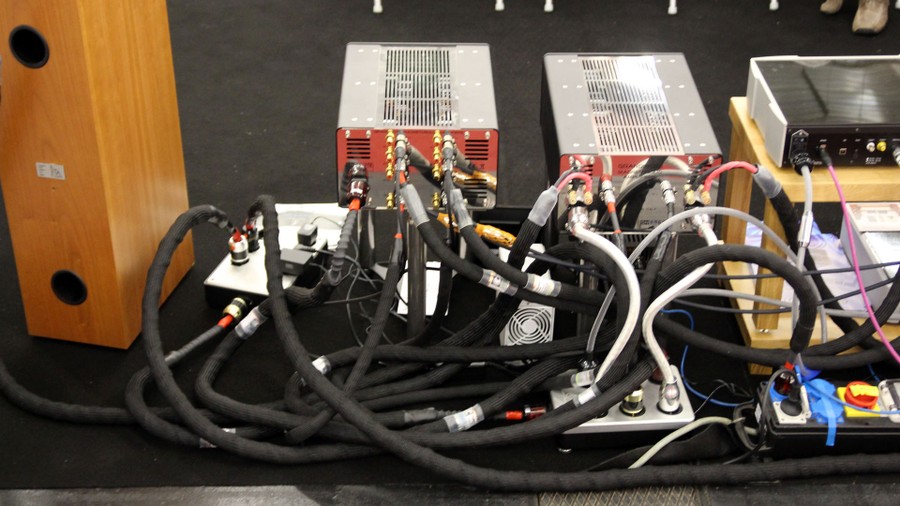
Abbildung 8: Wiring of a Hif System
Above you can see the high-priced wiring of a stereo system. The new price of the cabling is probably the equivalent of a used car - the technical sense of such a high-priced cabling is disputed among experts. After all, the wire cross-sections in the amplifiers or in the coils on the crossovers are considerably thinner than standard loudspeaker cables.
A sensible solution to the damping problem is the use of active loudspeakers. This not only gets rid of long cables between the power amplifier and the speakers - but also the much more disturbing crossovers.
Close loop control
In the past, some active loudspeakers were produced with regulated chassis. By means of an optical sensor or an additional voice coil, which induces voltages into a signal evaluation circuit according to its movement, the current oscillation is distinguished and corrected in case of overshoots. Appropriate control structures have already produced loudspeakers with a negative internal resistance.
The sense of the regulation is controversial for loudspeakers. In principle, the desired transmission obsolescence can also be achieved by controlling the crossover without regulation - especially DSP-based crossovers are very flexible and powerful.
If correctly designed, control can also suppress non-linear distortion caused by diaphragm omni-transformers. But there are also good low-distortion speakers without regulation.
Apart from the financial point of view there is at least nothing against the use of regulated loudspeakers, but the implementation of the complete loudspeaker should be considered.
More complex crossovers
With active loudspeakers, the complex impedance of the loudspeaker chassis is not part of the crossover. Any complex circuitry can be implemented for any perfect filter behaviour - without the damping factor suffering.
With passive loudspeakers there is inevitably an interaction between the impedance of the loudspeaker chassis and the crossover, which changes the filter behaviour - and worsens the impulse behaviour.
The currents and voltages in the active crossovers are not used directly to drive the loudspeakers but are only amplified by an output stage. Accordingly, the currents and voltages in the crossover are minimal - the coils and capacitors are tiny and inexpensive precision components. It is also possible to use operational amplifiers, e.g. to decouple filter elements from each other, making the design of the crossovers much easier.
With passive loudspeakers, the components are directly between the power amplifier and the chassis - they must be correspondingly resilient (large and expensive). If the components become too warm during operation, dynamic compression may occur.
Each component causes ohmic losses based on the higher currents - which of course applies especially to resistors. If different drivers with different efficiency levels are installed, the louder drivers must be slowed down with resistors to achieve a harmonious sound image. The superfluous power is converted into heat - and the efficiency drops. With active loudspeakers, this volume adjustment is done without power.
3 ways vs. 2.5 ways
Three-way boxes have various advantages over two-way boxes due to the targeted use of three drivers. It is possible to use drivers optimised for their frequency range much better than with two-way loudspeakers - which, if well designed, can result in significant advantages in terms of level stability or radiation characteristics.
With passive loudspeakers, however, the developer encounters considerable problems due to the interaction between drivers and the passive crossovers. The drivers do not have a constant resistance but are a highly complex frequency-dependent load. In an active loudspeaker, where the drivers are directly subject to the control of the amplifier output stage, this behaviour is not a problem.
Unfortunately, in passive loudspeakers, an interaction between the crossover and the complex load of the chassis cannot be prevented. Designing high and low passes with a good impulse response for a 2 way loudspeaker is much easier than designing a complete bandpass for the midrange driver, whose interaction with the crossover has strong parallelisms with gambling from the developer's point of view.
For this reason many manufacturers offer passively amplified 2.5 way speakers. These loudspeakers have
a tweeter
a bass-midrange driver which also takes over the bass.
a pure woofer which plays in the low frequency range parallel to the bass-midrange driver.
No bandpasses are necessary for this design - and the construction has the advantages of real three-way speakers, at least in parts. Some designers also speak of 2-way loudspeakers with integrated subwoofer when talking about 2.5-way loudspeakers. With active loudspeakers the "marrying" of three ways is a piece of cake. Active 2.5 way concepts are rare.
Protection circuits
The manufacturers of loudspeakers can quickly and accurately determine how resilient the loudspeakers are at high levels by taking appropriate measurements or temperature sensors at critical points. In the case of passive loudspeakers, they can include a warning in the instructions for use. In the case of active loudspeakers, protective circuits can be installed. Active loudspeakers equipped in this way are virtually indestructible.
Passive loudspeakers are very rarely equipped with protective circuits.
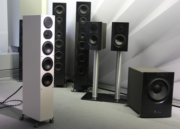
Figure 9: Nubert speakers
Figure 3 shows loudspeakers from the Nubert company. Nubert is one of the few manufacturers to supply passive loudspeakers with overload protection and rudimentary adjustments for room acoustics.
With some stereo amplifiers, an equalizer can be inserted between the preamp and power amplifier. By means of the correspondingly fine correction possibilities, e.g. to attenuate acoustic problems, passive loudspeakers can be turned into a kind of semi-active loudspeaker.
Digital control
The connection from source device to active loudspeakers is decoupled from the power supply of the loudspeakers and can be digital. This allows the use of digital error correction mechanisms which can regenerate the transmitted signal to 100%. Electromagnetic interference coupling into the supply cables is no problem even with long cable lengths.
Wireless signal transmission, for example via conventional WLAN, is also possible. Upgrade solutions are also available for this. However, cable connections for the power supply are still required.